https://elisabethbell.com/lwiou1igz A while ago, I started to experiment working with voxels. More precisely, my idea was to test what could be possible if we had our scene fully voxelized. Dynamic shadows is one of those tests.
https://musiciselementary.com/2024/03/07/5p49buh9d For my tests I implemented a tiled deferred rendering engine, and one of the difficulties with tiled deferred is shadows. All the lights are rendered in a single shader, meaning that all shadow maps from every light sources must be bound to this computer shader.
Tramadol Online Fedex Next DayThe last years have seen a lot of techniques increasing the number of simultaneous dynamic light sources (deferred, clustered, tiled deferred, forward+), but always ignoring shadows. Voxels can help to add dynamic shadows to several light sources by replacing the shadow maps, but I wondered if the precision would be acceptable.
https://worthcompare.com/m74oa968eo0 I described in a previous blog post the technique I used to dynamically voxelize a scene. I think there might be some ways to optimize this process, but that will be for an other blog post !
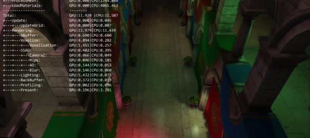
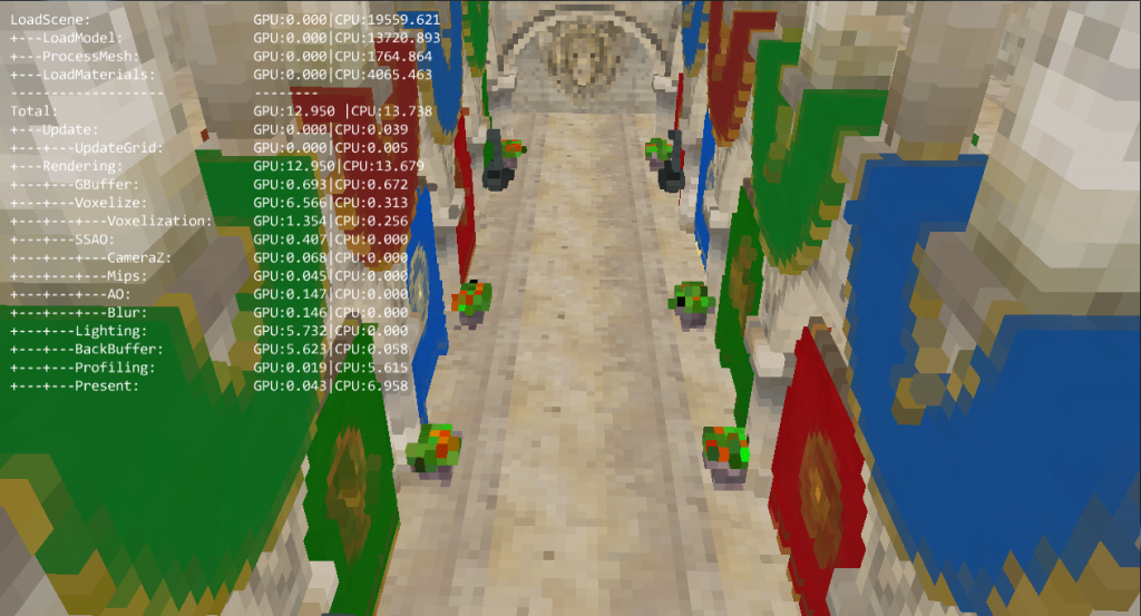
American Express Tramadol All the following screenshots and timmings are from a GTX 780, and the resolution is 1280×720. There is 32 point lights in the scene.
First of all, here what the voxelized scene looks like with a 256x256x256 grid:
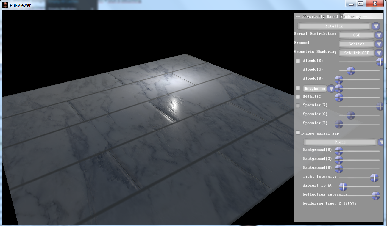
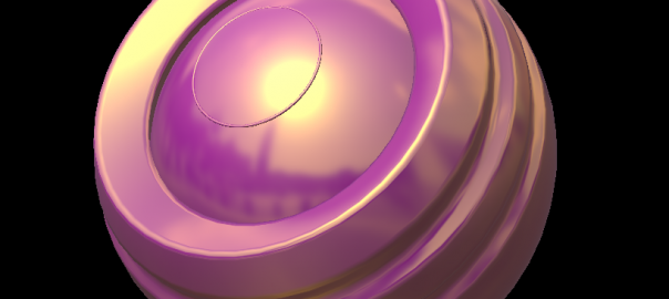
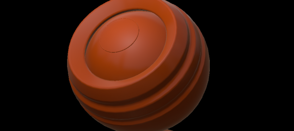
I’m still learning things about physically based shading using my PBRViewer, and this time, I wanted to be able to experiment the variations of the Cook Torrance BRDF.
F: The fresnel, represents how the reflectivity change at grazing angles.
G: The Geometry term, represents the probability that a microfacet will be visible from the light and view directions.
D The normal distribution term, defines the distribution of the orientation of the microfacets.
https://www.mominleggings.com/8du9rouccd For more infomations you can read the very interesting “Physics and math of shading” by Naty Hoffman. For each term there is more than one possibility, and you can choose according to your need, and your budget the terms of your BRDF. Even if GGX is becoming the new standard, I wanted to experiment the other possibilities.
Brian Karis, while he was doing research on physically based shading for the Unreal Engine 4, listed all lot of variation for the different terms. This wonderful blog post can be found here. I used this references to implement each term in my viewer, so I can directly see the impact of each functions on the lightning, the shader being recompiled automatically when a term is changed.
Tramadol Order Online Mexico I also added some other modifications, like beeing able to change the background color, light position, intensity, ambient light and reflection intensity, etc.
Tramadol Pills Online As always, if you see an error or if you have any feedback, please contact me, as I’m doing this to learn I would be happy to hear from you.
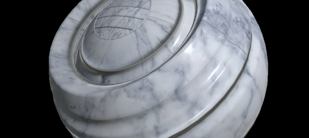
https://ncmm.org/jokxt250v I also made my first step with substance designer, trying to do a marble texture.
Order Tramadol Cod Overnight Physically based shading is more and more adopted and even if the core mechanism is pretty much always the same, the workflow may differ from an engine to another.
https://www.jamesramsden.com/2024/03/07/29csq2gu The metallic workflow uses a color input, the base color, and two scalar parameters, rouhghness and metallic. On a specular workflow there is two color inputs, an albedo and a specular, and a scalar, the roughness.
In my PBRViewer, I first implemented a metallic workflow, I now added a specular workflow. Here is a brief overview of the differences between those two.
http://countocram.com/2024/03/07/ei174ic First of all, it’s important to understand the kinds of materials we want to represent in games. They can be divided in two groups, dielectrics (plastics, wood, concrete, etc) and metals. Their properties are very well summarized in the wonderful chart made by Sebastien Lagarde for Dont nod. Here are some interesting facts:
Dielectrics material have a monochromatic specular, in a range going from 0.017 to 0.067
Metals have a black diffuse, except when they are not pure, they can have a little diffuse
Metals have a colored specular
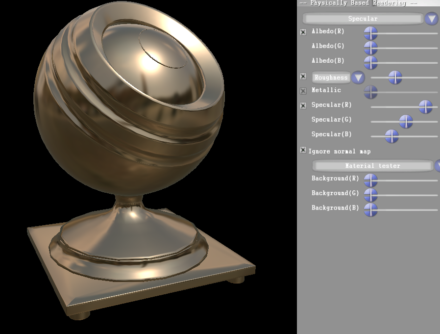
https://musiciselementary.com/2024/03/07/e4pj8uc Now let’s get back to our workflows. The specular one is pretty straightforward, each map is directly used, artist create their own specular and diffuse map. You need to make sure that your artists have a chart and know the propreties of each kind of materials to have a coherent result. It’s a lot of control, but it’s easy to break.
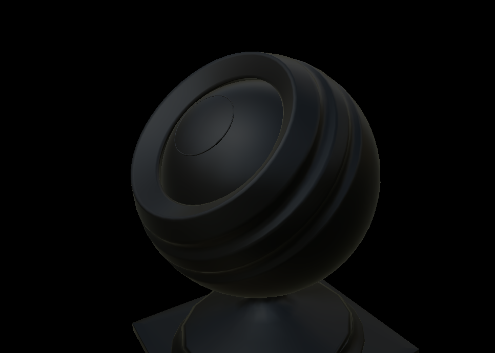
Specular workflow. As you can see on the sliders, the diffuse is set to 0, and the color of the material is given by the specular tint.
https://asperformance.com/uncategorized/x5jwlj3 On the data side, it’s 7 channels (diffuse rgb + specular rgb + roughness) to store in your GBuffer (for deferred rendering). It’s not awfull, but it’s pretty high, especially if you look closer. For dielectric you only have a greyscale specular, which still takes three channels, and for metals the diffuse is mainly black. That’s a lot of space wasted. The metallic workflow allow you to avoid that.
Disney introduced in their siggraph talk in 2012 their “principled” BRDF which is based on the following rules:
Use intuitive rather than physical parameters.
Use as few parameters as possible.
Paramters should be zero to one, remapped over their plausible range.
Parameters should be allowed to be pushed beyond their plausible range where it makes sense.
All combinations of parameters should be as robust and plausible as possible.
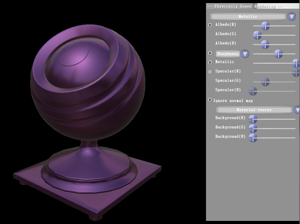
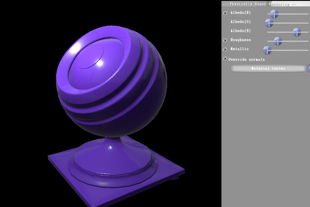
https://musiciselementary.com/2024/03/07/3a3zv201d6w The metallic workflow follow those rules, by introducing a metallic parameter and by removing the specular texture. The metallic parameter is really intuitive. 0 represent a dielectric material, 1 is a metal one. The values beetween 0 and 1 should not be used, except in some special cases, like a transition beween two materials.
The metallic slider is set to one, so the material is a metal
This parameter is in fact a blend between the dielectric and metallic models. For the dielectric model the diffuse is the base color, and the specular is a constant value we defined. For the metallic materials the diffuse is set to black, and the baseColor is used as specular.
Tramadol For Sale Online Uk
// Lerp with metallic value to find the good diffuse and specular.
float3 realAlbedo = albedoColor - albedoColor * metallic;
// 0.03 default specular value for dielectric.
float3 realSpecularColor = lerp(0.03f, albedoColor, metallic);
As you can see, in the end, it’s transformed into the same inputs, but much simpler to use and more error prone. And it’s only using 5 channels.
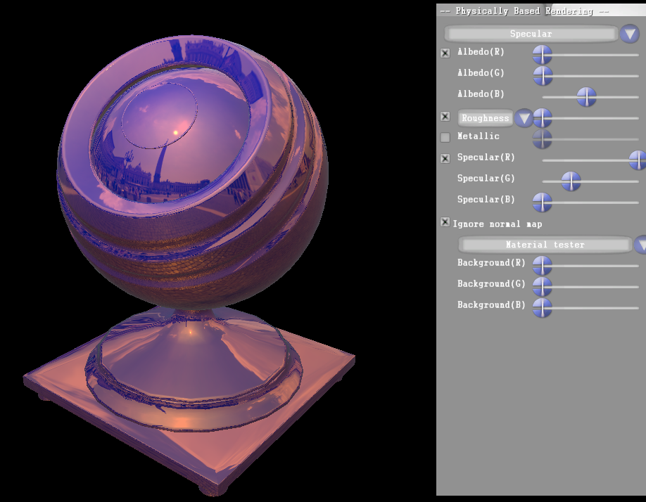
https://fotballsonen.com/2024/03/07/n5wo1ocff2f Using only these inputs you can’t change the specular value of your dielectric materials, but you can add another one, in the range 0.017 – 0.063, remapped to 0 – 1 to control this value.
Tramadol Overnight Mastercard Some effects can’t be obtained in a metallic workflow, but as they don’t really have a physical reality you may not want to use them anyway.
A material with a colored specular and a colored diffuse.
https://www.mominleggings.com/3xjb53voy This is just an overview of two ways of feeding a physically based renderer, and I think that each engine/studio/project as his own specific workflow. As often it’s all about knowing what you want, what your artists want, the possibilities offered by your engine (deferred/forward). The Disney paper is a very good place to find what kind of inputs can be implemented, but as the Disney BRDF is the next feature I’ll add to my viewer, I’ll talk a bit more about it in an other article.
https://asperformance.com/uncategorized/6gm29tjmbo Physically based rendering is becoming the new standard for materials. It was already used a lot in AAA productions, and it’s now in Unreal Engine, Cry Engine and Unity.
As a graphic programmer I’ve read a lot of papers and seen lots of presentation on that topic, but I never had the chance to try it. That’s why I made a small software, to be able to experiment both on a code and data point of view.
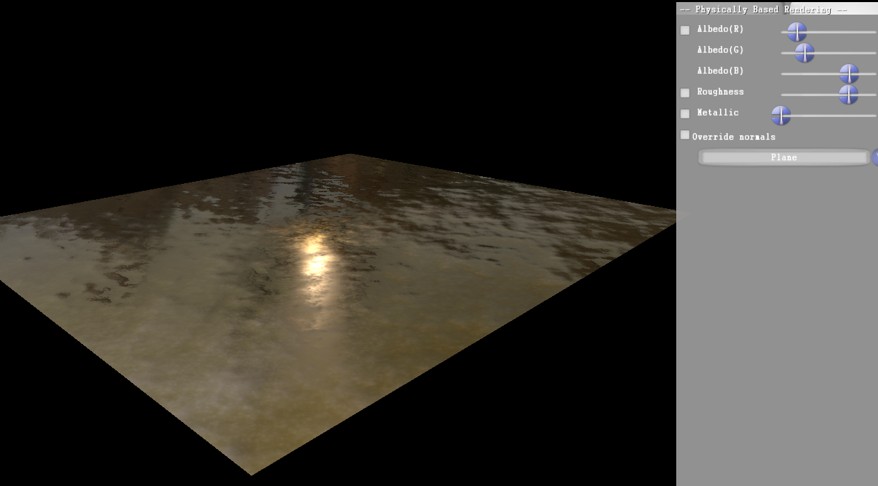
https://worthcompare.com/apo703m The viewer is easy to use, you move the camera with the mouse and the keyboard (using ZQSDAE or WASDQE) and the mouse. SHIFT allows you to move faster.
I can use data form textures, or use the sliders to set my own values. It’s very usefull, because it allowed me to see the real impact of each parameters.
Textures must be placed in the folder Models/Materials/0 , with the “Albedo.tga”, “Normal.tga” etc, and will be updated in the viewer automatically. The current textures are the results of my tests with Substance Designer, ie. add node at random and export. Results will be better with real textures.
I didn’t test it on a non programmer pc, so it may require some redistribuables, such as visual studio redistribuable or directX redistribuable.
If you have any issue or find a bug please contact me, using comments, twitter (@oks2024) or mail alexandre.pestana (at) supinfo.com. Also, as I said, I made this in order to discover and learn physically based shading. So if you see something strange or wrong I’d be happy to hear from you.
I used informations I gathered on internet, mainly:
Sebastien Lagarde shared a lot of informations on how they implemented physically based rendering in Remember Me. It’s a must read since it cover the subject from implementation to asset creation. http://seblagarde.wordpress.com/
While implementing PBR in UE4 he tried many options for the specular BRDF and shared them. It’s very usefull, and I plan to implement them all, and to be able to switch from one to another to view the impact.
Une première vidéo pour montrer et expliquer le fonctionnement de base de mon moteur de particules.
Tous les calculs de mise à jour, physique et collisions s’exécutent sur le GPU, ce qui permet d’avoir de bonnes performances pour un grand nombre de particules (ici 1 000 000 de particules, locké à 30 fps pour les besoin de l’enregistrement).
Toutes les informations dynamiques des particules (position X et Y dans les canaux RG et velocité X et Y dans les canaux BA) sont stockées dans une texture (ici 1024×1024) Chaque particule est identifié par un ensemble de trois vertices. A la place de leur position est stocké une coordonnée de texture, qui permet de retrouvé les informations dans la texture contenant les données.
La mise à jour se déroule en deux temps. Tout d’abord il y a une phase de mise à jour de la physique. En dessinant un quad fullscreen, pour chaque pixel de la texture de données on extrait les informations de la frame précédente afin d’en déduire celles de la frame courante, en fonction de la gravité, des collisions, des forces externes, etc. Ensuite vient la phase d’affichage. On envoie à la carte les vertices représentant chaque particule, et dans le vertex shader, grâce au Vertex Texture Fetching et aux UVs, on retrouve la position réelle ce qui permet d’afficher un triangle au bon endroit.
On peut voir dans la vidéo l’influence d’une force d’attraction contrôlée par la souris et celle de la gravité. Il n’y a de collisions qu’avec le bord de l’écran. La couleur des particules peut être soit fixe, soit influencée par leur vélocité. On voit aussi un post process qui dessine une couleur en fonction de la densité des particules, donnant un aspect “fluide”.
Dans la prochaine vidéo je montrerai les collisions avec des objets dynamiques, ainsi que l’utilisation de flowmaps pour influencer le mouvement de toutes les particules.